THIS PAGE CONTAINS PROPRIETARY INFORMATION WHICH MUST NOT BE USED FOR COMPETITIVE PURPOSES OR IN ANY WAY DETRIMENTAL TO BETE FOG NOZZLE INC. ©BETE FOG NOZZLE, INC.
A HIGH INTEGRITY,
SIMPLE ACTION PIPE JOINT
E.J. Nobles, BSc, MSc, PhD, CEng, MIMechE
G. Thompson
Department of Mechanical Engineering,
University of Manchester Institute of
Science and Technology
SYNOPSIS Flanged joints are the most common type of remarkable
pipe joint and, given the correct gasket and bolt loading, their application
is usually successful. However, there are certain circumstances arising out
of operational considerations where an alternative jointing method is needed.
External corrosion can make bolt removal difficult, gaskets can be over or under
tightened by poor fitting practice, and the mass of the flange may be structurally
undesirable. This paper and long term integrity are not sensitive to the skill
of the maintenance personnel. The design concepts are first given leading to
thte description of the coupling itself. To verify the structural integrity
of the coupling, an experimental stress analysis of the device has been performed
under combined loading: pressure, bending and shear force. An account of field
experience concludes the paper.
1.
INTRODUCTION
Remakable pipe joints are widely recognised as a significant source of maintenance
expenditure, particularly when pipelines have to be regularly broken to permit
cleaning or inspection (1,2). Flanged joints are the most common type of remakeable
pipe joint and, given the correct bolt loading, their application is usually
successful. The make and break time for a flange largely consists of the time
taken to tighten and release the bolts plus the time taken to clean up the flange
faces ready for a new gasket. If there is extensive external corrosion then
bolted connections can be very difficult to release and maintenance times can
become excessive. Even without a corrosive environment flanged joints can give
rise to difficulties. Gaskets can be over- or undertightened, both cases giving
rise to leakage.
There are a wide range of remakeable pipe joints commercially available,
ranging from V clamp designs to quick release couplings which are commonly
used in hydraulic and pneumatic systems. The types that have found more common
application in process plant applications use bolted connections (axial or tangential)
to provide a force to grip the plane outside diameter of a pipe. Often, one
finds resistance to the use of jointing methods which rely on a friction grip
rather than on a positive location, especially if significant axial forces and/or
bending moments are applied to a pipe since the seal may be affected.
Therefore, there is a need for a pipe coupling which will meet the following
requirements: the coupling should have a simple action suitable for use in
an internally and .or externally corrosive environment, and should provide a
high integrity joint under complex loading. This paper discusses the design
of a pipe joint to meet these requirements, and presents the results of a test
of the device under combined loading: pressure, bending and shear force.
2.
DESCRIPTION OF THE PIPE COULPING
2.1 Design
principles
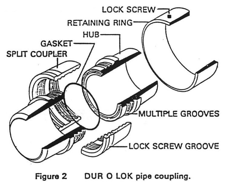
The Dur O Lok coupling, shown in figure 2, was originally designed by Hitz
as a compact high pressure coupling for pipelines and pressure vessel closures
(5). It uses a self-energizing seal with the result that it is not necessary
to provide a high contact force between coupling halves to make the seal effective.
This eliminates the greater part of the high compressive force which is a feature
of flange design. Indeed, many problems experienced in flange usage can be
traced to incorrect bolt loading due to bad fitting practice.
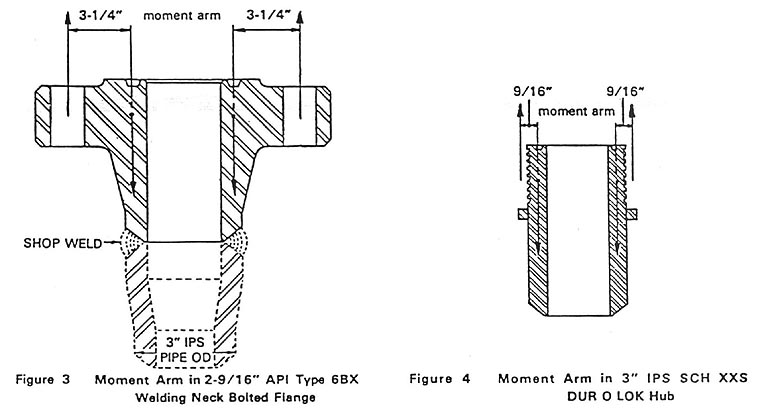
Consider the case of a 3 in class 1500 ANSI flange, see Fig. 3. The
bolt load is applied at a moment am of 61mm (2.5) relative to the mid thickness
of the pipe wall. In order to minimise the distortion of the flange faces and
to keep stresses to a safe level, a large flange thickness is specified. However,
such large material sections create metallurgical, thermal transient and handling
problems. Excessive stresses can be created in the bolts, flanges or gasket
due to a combination of any of the following: initial bolt load, hydrostatic
end load, thermal loading (6). A common case of flange failure is permanent
distortion of the flange due to uneven bolt loading around the joint circumference
which causes leakage. Correct bolt loading is therefore a pre-requisite to
successful flange usage, and heavy sitff components are a feature of flange
design.
In contrast, consider the design of a 3 schedule 80 Dur O Lok coupling
which meets the same specification as the flanged joint given above. The axial
location is provided by the interlocking of the split coupler with the multiple
grooves, see fig. 2 The moment arm of the axial forces about the mid thickness
of the pipe wall is 6mm (0.25), see Fig. 4, which is one tenth that of the
bolted flange. Thus, combined with complete circumferential distribution of
the forces, distortion of the sealing faces of the coupling is not a problem
and a smaller lighter coupling results. Figures 3 and 4 are drawn on the same
scale for comparison.
The self-energized seal must be located in a dimensionally stable cavity
if it is to be effective. The axial length between the loading faces either
side of the seal is 10mm (0.4). For a rating of 170 bar (2500 lbs/in2)
at 340°C (644°F) the expansion of this dimension is 0.05mm (0.002). Note that
under the same conditions the bolt stretch in the equivalent ANSI flange is
0.5mm (0.02).
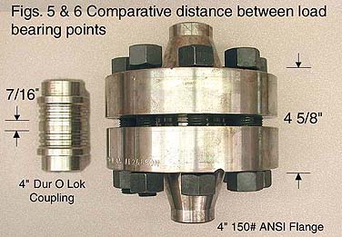
The net effect of the design approach is a reduction in the normal flange
diameter of 267mm (10.5) to a coupling diameter of 124mm (4.9) and a corresponding
reduction in length from 254mm (10) to 168mm (6.6). The weight of the connection
assembly for the 1500 ANSI flange is 544 N (122lbf) as compared to 55N (12.4lbf)
for the steel Dur O Lok couplings.
2.2 Detail
Design
The detail design is illustrated in Fig. 2 as an exploded view, the assembled
components are shown in Fig. 4. The hub section progressively thickens from
the pipe wall thickness to its maximum to eliminate stress risers. A specific
tooth and groove form has been adopted from that used in joining threads for
oil well drilling work. The front angle of the tooth is designed below the
angle of friction for all the metal involved. Thus, separating forces will
not tend to separate the couplers even if the retainer ring is removed. The
back of the tooth has been designed at an angel that assures a perfect tooth
fit without possible wobble or lost motion in a situation of vibration. Note
that the coupler sections are designed with a gap between the ends to further
assure complete seating of the special tooth in the hub grooves. Tests of the
engagement by blueing methods demonstrate over 90% of total area contact which
is created by machining tolerances of 0.025mm (0.001) to 0.05mm (0.002).
The retainer ring has a small angle which forces the coupler sections
into full engagement of tooth and groove. The effect of the two angles of the
retainer ring and hub tooth working in unison provides a mechanical advantage
of 150 to 1 for driving parts into total engagement. Anchoring set screws in
the retainer ring engage a reverse taper. They are made of a non-corrosive
stainless to insure against any possible back away of the retainer ring or thread
jamming. The set screws are designed to be flush with the outside of the ring.
It proves correct assembly of parts and full engagement of holding grooves to
the craftsman and supervisor.
The seal is located in a groove machined into one face of the coupling.
At lower temperature services a standard elastomer O-ring seal is used, whilst
at higher temperatures a metal to metal (omega) seal is called for. For extremely
high temperature service conditions an over-centre seal is specified.
2.3 Maintenance
procedure
Each half of the coupling, welding into the pipeline, is brought together approximately
into the required position and the retaining ring slipped into the required
position and the retaining ring slipped onto one half. The seal cavity and
mating surface are checked for cleanliness, and the appropriate seal inserted.
The fitted seal stands just proud of its cavity to ensure adequate compression
for an initial leak free assembly. The hubs are then brought together into
reasonable alignment. Manual or hydraulic tools can be used if necessary, location
for which is provided by the two ledges. The split couplers are placed in position,
they may be tapped into place. Finally, the retaining ring is slipped over
the split couplers and lightly driven up flush with the coupling ledge using
a soft hammer and the locking screws run up. This is not a difficult task.
If the split couplers are incorrectly positioned then the retaining ring will
not pass over them.
The above steps are all sequentially self -checking. In practice the
coupling is simple to make and break, and tends to give one confidence that
a secure joint has been made.
3.
COUPLING INTEGRITY
3.1 Failure
criterion
It is necessary to establish a failure criterion for the coupling before
intiating a test procedure. A pipe coupling may be deemed to have failed when
leakage begins. However, a significant leak in one application may not give
cause for concern in another. For example, a leak rate of parts per million
in an inert gas test would be inappropriate for a general purpose steam line.
In this study, a significant leak was defined as one which could be detected
visibly using water as the pressurising medium. This test was considered to
be generally suitable for process plant applications.
Leaks may be caused by changes in dimensions as the coupling strains,
or by the structural failure of a component. It is not possible to determine
changes in the dimensions of the assembled coupling parts therefore nearness
to failure in this respect cannot be identified, only the failure itself.
However, the surface stress levels in the coupling components can be measured
using electrical resistance strain gauges. Thus the maximum shear stress may
be used to estimate how close components are to yielding (von Mises yield criterion).
3.2 Test Procedure
It was known that the coupling could withstand a simple hydrostatic test
to 1600 bar (23500 lb/in2) without leaking (7). Leak detection was
as described above. No components were observed to have suffered permanent
deformation in that test, but no stress levels were measured.
Rarely do couplings suffer conditions of simple hydrostatic pressure in
plant use. It is necessary to know how a coupling will behave when subjected
to bending and shear forces. Typically these may arise if the coupling is subjected
to an overhung load during maintenance (say if a section of pipe is broken),
or when a pipeline shifts under service loading (temperature, pressure).
A test rig was constructed which could apply a bending moment and shear
force to a pressurised coupling. Two lengths of 75 mm (3 in.) diameter steel
pipe were joined by a Dur O Lok coupling, the ends were closed by ANSI 150 flanges
through which the pipe was pressurised and vented. One half of this assembly
was held and a point load applied near the opposite end, see fig. 5. Thus one
length of pipe acted as a cantilever with an end load, and the Dur O Lok coupling
was subjected to a bending moment and a shear force in addition to internal
pressure.
Strain gauge rosettes were mounted at intervals around the circumference
of the coupling: on the hub, on the ledge, and around the ring. An initial
test was carried out in which the internal pressure was progressively increased
to 24 bar (350 lb/in2) with no external loads applied. Strains were
recorded as the pressure increased. The test assembly was then pressurised
to 24 bar and the transverse end load progressively increased to 10 KN (2 ton).
The 10 KN load gave an in-plane bending moment of 6.4 KNm (9400 lb ft.) at the
centre of the coupling. The shear force is of course 10KN. Strains were recorded
as the transverse load increased. All tests were carried out at room temperature.
3.3 Results
The pressure test to 24 bar produced very little strain in the coupling
(< 70 µ on all gauges) and no strain plot departed from linearity. No leakage
was observed.
The combined loading of 24 bar internal pressure, 6.4 KNm applied moment
and 10 KN shear force caused no leakage from the coupling. All parts of the
coupling were re-usable, and no leakage was observed from repeat tests under
these conditions even using the same elastomer seal. No departure from linearity
was found in any strain plot. The strain induced in the coupling resulted from
the external loading primarily. The largest stress was found on the compression
side of the hub: the minimum principal stress was -214 MN/m2 (31,130
lb/in2) giving a maximum shear stress of 181 MN/m2 (26,000
lb/in2). The strain levels recorded on the ledge were an order of
magnitude smaller, and those on the ring smaller still. The maximum shear stress
found is clearly insufficient to cause yield.
As a comparison, the calculated maximum stress in a 75 mm (3 in.) pipe
due to a bending moment of 6.4 KNm and an internal pressure of 24 bar is 408
MN/m2 (59400 lb/in2). The hoop stress due to internal pressure is
16 MN/m2, (2300 lb/in2). The lower stress levels found
experimentally are due to the increased thickness of the coupling.
3.4 Summary
Under the combined loading of 24 bar internal pressure, 6.4 KNm in-plane
bending moment and a 10 KN transverse load, the coupling proved leak tight and
suffered no permanent deformation.
4.
FIELD EXPERIENCE
The coupling has found application in a wide range of industries. Within the
first two years of marketing, over 300 units have been placed in service and
applications include the following.
In the refining industry, the smooth bore and close alignment is especially
valued in soldis transport lines. Maintenance problems have been reduced in
the chemical and other process industries, especially where joints have to be
made and broken regularly for cleaning and inspection. Research and development
companies have found in the coupling unique flexibility to solve many problems.
Dur O Lok pipe couplings and closures are being increasingly specified by engineering
contractors. The list of users in these categories includes many well known
international companies.
To date, there has not been a single mechanical failure reported in any
installation. Only a few problems hve surfaced with regard to seals but they
have been solved as they appeared. This has led to improved operability and
better definition of seal materials. Upon leakage of a seal, the leak has never
been in the form of a jet and there has been no destruction of the mechanical
structure. Also, experience has shown that adjustment is not required as a
result of operating pressure or temeperature flutuations.
During the initial marketing period several improvements have been incorporated
into the design, including additional advantages such as:
(i)
Development of an interchangeable elastomer and metal to metal omega seal.
This simplifies dealer and maintenance stocking as only a single type of hub
is needed.
(ii)
Development of a design with interchangeable orifice and blank plate.
(iii) Development
of a clean out fitting for refinery use in fired heater or serpentine coils.
(iv) Development
of tell-tale device on the hub blocking the retainer ring to meet code requirements
for lethal gases and liquids.
5.
SUMMARY
The Du O Lok coupling is a simple action high integrity pipe coupling
which is suitable for use in a wide range of piping systems including hazardous
duties. The coupling may be made and broken simply which reduces maintenance
costs. When compared to a flanged joint for the same duty, it is easier to maintain,
forms a good seal easily which is less sensitive to pressure-temperature fluctuations,
is lighter and more compact, and is competitively priced.
Under a combined loading test of an internal pressure of 24 bar (350 lb/in2),
an in-plane bending moment of 6.4 KNm (9400 lb ft.) coupling did not leak and
did not suffer any permanent deformation. When subject to a simple hydrostatic
test, the coupling will withstand a pressure of 1600 bar (23500 lb/in2)
without leaking.
REFERENCES
1.
Report No. MD20767, Mond Division (Eng. Dept.), Proc. Of University/Industry
Information Exchange, Runcorn, England July (1979).
2.
SEWARD, D.N. Anomalies of boltings. Petroleum Review pp. 35-37
(1976).
3.
COTTRELL, B. the split nut. Chartered Mechanical Engineer pp.73-76
Nov. (1978)
4.
LEE, F.O.Y. A design study to reduce the maintenance costs of pipe joints,
MSc Dissertation, UMIST (1980)
5.
VAN TASSEL, D. H. and HITZ, G. L. Design of compact, high pressure
couplings and closures for pressure vessels and piping. Pressure Vessel and
Piping Conference, ASME, Orlando, Florida, June (1982)
6.
ASME Boiler and Pressure Vessel Code. Section VIII, Division 1, (1980).
7.
Test report No. 82-29763. Midstates Analytical Laboratories Inc. Tulsa,
Oklahoma, U.S.A. (1982).
THIS PAGE CONTAINS PROPRIETARY INFORMATION WHICH MUST NOT BE USED FOR COMPETITIVE PURPOSES OR IN ANY WAY DETRIMENTAL TO BETE FOG NOZZLE INC. ©BETE FOG NOZZLE, INC.