THIS PAGE CONTAINS PROPRIETARY INFORMATION WHICH MUST NOT BE USED FOR COMPETITIVE PURPOSES OR IN ANY WAY DETRIMENTAL TO BETE FOG NOZZLE INC. ©BETE FOG NOZZLE, INC.
DESIGN OF COMPACT, HIGH PRESSURE
COUPLINGS AND CLOSURES
FOR
PRESSURE VESSELS AND PIPING
by
David H. Van Tassel, P.E.
And
Gifford L. Hitz
ABSTRACT
This paper presents the design and details of a pipe joint
and closure for use in a wide variety of pressure vessel and piping applications
including: petrochemical, marine, nuclear, electric utility and synfuel, in
low as well as high pressure. The pipe joint consists of a pair of hubs locked
together by a multi-grooved split coupler retained, in turn, by a tapered ring.
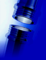
FIGURE 1 3 1500 lb ASA Flange vs. Equivalent
3 DUR O LOK pipe joint.
Comparison is made to a bolted flange demonstrating
that the grooves direct forces through the coupling in a manner resulting in
a substantially reduced level of stresses effectively eliminating the causes
of leakage in bolted flanges. This method of load transmission further results
in a compact coupling of significantly reduced weight and size, Figure 1, yielding
numerous advantages over not only bolted flanges, but also, other couplings.
INTRODUCTION
Closures for pressure vessels and joints for
piping introduce problems which are undoubtedly as old as the use of vessels
and pipe. Pressure vessel rules and flange standards have received regular
review and revision down through the years. However, most of the revisions
in pressure vessel rules and the flange standards have centered around standardization
of dimensions and calculations and updating material properties rather than
conceptual improvements in joint design.
While in the majority of designs the practice
of the past should be adequate (1), there exist admitted shortcomings in the
conventional bolted flange. These are evidenced not only by the discussion
of such in Appendix S to Section VIII of the ASME Boiler and Pressure Vessel
Code, but also by the various day-to-day experiences within industry. As typical,
when a synfuel pilot plant started full operation there were problems related
primarily to pipe joints the difficulties were described as leaks which made
it impossible to maintain pressure in portions of the plant (2).
Troubles with bolted flanges are further demonstrated
by design efforts over the years to devise connections which overcome their
failure. These efforts generally fall into one of four types:
1)
Clamp
2)
Collet
3)
Shear Ring
4)
Shear Pin
and they utilize one of two methods of containment:
1)
Bolts or threaded pins
2)
Tapered rings or pins
The design effort by the authors is basically a clamp type coupling utilizing
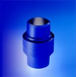
multiple shear members and a tapered ring, Figure 2.
Figure 2 DUR O LOK pipe coupling.
DISCUSSION
The Problem
Having established that a problem exists with
bolted flanges in some services, let us examine that problem and then, more
importantly, its source in order that we might seek an orderly solution.
Leak. The most popular connector used in
industry is the bolted flange, however, in many applications the recurring problem
is that they leak. Granted, there are situations where this is nothing more
than a minor inconvenience, but, certainly there are no services where a leak
is desirable.
The leaking problem originates with the basic
design of bolted flanges the hydrostatic separating or end forces are transmitted
through a circuitous path, Figures 3 and 4. The resultant moments create bending
stresses which require thick flanges and heavy hubs. In turn, these
Figure 3 Moment Arm in 2-9/16 API Type 6BX
Welding Neck
Bolted Flange
large material sections create metallurgical, thermal transient,
handling (weight and space), operational and overall economic problems (3).
The moment increases rapidly for larger diameters and higher pressure, restricting
the practical, leak-free use of this design.
Appendix S to Section VIII, Division 1 of
the Code gives an excellent discussion of certain practical matters to be taken
into consideration in order to obtain a serviceable design for bolted flange
connections (1). These considerations center around the bolts, the flanges
and the gasket the three components of a bolted flange connection. Excessive
stresses can be generated in any of these three components by any combination
of three loads: the initial bolt load, the hydrostatic end load generated by
internal pressure and the load caused by thermal differentials. Each of these
is transmitted by all three components of the joint.
In the case of the bolts, excessive initial
bolt load can introduce the problem of yielding in the bolting itself, which
can occur in the tightening operation to the extent of damage or even breakage.
Any additional load generated when internal pressure is applied can produce
further yielding with possible leakage. An appreciable differential in temperature
between the flanges and bolts or, a different coefficient of thermal expansion
may cause an increase in bolt load which, when added to the load already existing,
can result in yielding of the bolt. Whereas, any pronounced decrease due to
such effects can result in such loss of bolt load as to be a direct case of
leakage. In either case, retightening of the bolts may be necessary, but it
must not be forgotten that the effects of repeated retightening can be cumulative
and may ultimately make the joint unserviceable.
Excessive bolt load, whatever the reason,
may cause the flange to yield, even though the bolts might not. One of the
most prevalent flange failures is irregular permanent distortion of the flange
due to uneven bolt load around the circumference of the joint, causing the flange
face and its gasket contact surface to warp out of a plane. This yielding is
due to the bending stress, Figure 3, usually the highest stress in the flange.
The gasket, too, can be overloaded, even without
excessive bolt loads, because the full initial bolt load is imposed entirely
on the gasket. Accordingly, consideration must be given to prevent gross crushing
of the gasket (1).
Figure 4 Moment Arm in 3 IPS SCH XXS
DUR O LOK Hub
Objectives
As the authors studied the problems encountered in vessel closures and pipe
joints the following objectives were established are now realized:
-Design a smaller diameter joint to increase pipe rack utilization and simplify
clearance problems.
-Design a lighter weight joint capable of matching full pipe strength.
-Utilize a true self energized seal as a simple replaceable element at each
make-up of the joint.
-Eliminate bolt stretch and provide positive assembly not requiring special
skill.
-Reduce the possibilities for jamming or galling of parts
on disassembly. Eliminate use of threads and super finished surfaces.
-Minimize the effects of uneven heating, rapid temperature change or pressure
variation.
-Design a pipe joint in conformance to all applicable existing provisions of
the code.
Means of Solution
As there are three components where problems
with bolted flanges arise, the solution to the problem rests in affecting changes
with these three.
First, the bolting is replaced by a multi-grooved
split holding coupler. The coupler replaces the possibility of the excessive
initial bolt load as it has a predetermined level of stress defined by the geometry
of the grooves. The coupler also minimizes the possiblity of thermal loadings,
due to the fact that it is in intimate contact with the hubs at the outside
diameter of the piping as opposed to bolts in oversized holes at a significantly
larger bolt circle. In addition, the coupler has approximately twice the cross-sectional
area of the bolts in joints of equal ratings, in most cases matching pipe strength,
effectively reducing stress levels. Aside from these improvements, the most
significant advance is the reduction in the distance between the load reaction
points; that is, the length of the bolting or coupler subject to elongation
and relaxation
Figure 5 Distance Between Load Bearing Points in
a DUR O LOK
Coupling
caused by the initial bolt load, hydrostatic end load and
thermal load. In even the most extreme services, this length in the coupler
is a fraction of an inch, Figure 5; whereas, in the large high pressure bolted
flanges this length exceeds one foot, Figure 6.
Second, the flanges are replaced by multi-grooved
hubs. The problem of the high bending moments in flanges is alleviated by arranging
the load bearing surface in a multiplicity of levels similar to a gun breech
lock. This does not require a separate or special end forging, it can be machined
directly in the cylinder wall and dismantling is a quick and simple opening
and reclosing (4). The high bending movements in bolted flanges are reduced
to an insignificant level and the design basis becomes the more easily defined
shearing and bearing stresses in the multiple grooves.
Finally, the typical gasket requiring a high
seating stress is replaced by a true self energized gasket. Two pressure energized
gaskets are furnished: One, a proprietary overcenter metal gasket for high
temperature, critical or long-term service and the other, an O ring gasket
for low temperature service. These gaskets are easily replaced and obviate
the need for carefully finished seats. There is no danger of gross crushing
or short-term relaxation of these gaskets the initial seating is predetermined
by the geometry of the grooves and the seal is maintained by internal pressure.
The exact defined and constant geometry of the gasket cavity makes all this
possible.
THEORETICAL EVALUATION
In the calculation of bolted flange stresses,
the moment of a load acting on the flange is the product of the load and its
moment arm. The moment arm is determined by the relative position of the bolt
circle with respect to that of the load producing the moment (1), Figure 3.
Figure 6 Distance Between Load Bearing Points in
A 10 2500 lb.
ASA Flange
As previously discussed, the design presented in this paper
is directed toward significantly reducing these moments by minimizing the moment
arms. This is accomplished by locating the load bearing surfaces as nearly
in alignment with the load as possible, Figure 4. Accordingly, the coupler
groove diameter is significantly less than the bolt circle diameter of an equivalent
bolted flange.
Calculation of these moments yields an enlightening
comparison between a bolted flange and the subject coupling. The moments for
a 2-9/16 inch API type 6BX Welding Neck Flange for 15,000 psi and the comparable
3 inch XXS Dur O Lok coupling were computed (Appendix). These computations
demonstrate that high bending moments, the major source of leaks in bolted flanges,
have been significantly reduced by the coupling design; evidenced by a reduction
in the total moment to approximately 7% that of the bolted flange, Table 1.
| |
2-9/16
API
Type 6BX
|
3
IPS SCH XXS
DUR
O LOK
|
|
Moment
|
in-lb
|
In-lb
|
|
MD
|
157098
|
33512
|
|
MG
|
277270
|
0
|
|
MT
|
263823
|
12990
|
|
MO (operating)
|
698191
|
46502
|
|
MD (gasket seating)
|
647062
|
0
|
TABLE 1 Comparison of Moments in API Type 6BX
Flange and DUR
O LOK
The fundamental design concept of the coupling
presented in this paper is the reduction of stress levels and stress concentration.
In addition to the reduced stresses resulting from the reduced moments, the
stresses are distributed more evenly. The bolted flange shows increased stress
levels at each bolt location, whereas, the design presented in this paper maintains
a uniform stress level around the entire circumference of the coupling, without
the possibility of mechanical differences in bolt and nut make up.
As a practical matter, axial shear stresses
and bearing stresses are the stresses to be considered in designing the couplings.
By increasing the number of grooves provision can be made for additional loading.
Therefore, both the hub and the clamping couplers can be conservatively designed
to accommodate high external loads in addition to pressure loads.
The most prevalent cause of leaking in bolted
flanges, as pointed out in Appendix S of the ASME Code Section VII, Division
1, is the elongation of the bolts due to high initial bolt load, pressure increases
or thermal cycle during service. The elongation due to hydrostatic end force
(pressure) is calculated (Appendix) according to conventional strength of materials
theory, Table 2
| |
2-9/16
API
Type 6BX
|
3
IPS SCH XXS
DUR
O LOK
|
| |
in.
|
in.
|
|
length subject to elongation
|
4.500
|
.355
|
|
elongation
|
.01044
|
.00015
|
TABLE 2 Comparison of Elongation in API Type 6BX
Flange Bolts and
DUR O LOK Couplers
While such elongation may appear small, a molecule of gas
may be as small as .001 micron. Thus, if a gasket takes a permanent set, gas
can readily leak through a gap of .002 inch. The coupling presented in this
paper utilizes a pressure of self-energizing gasket which, together with an
elongation 1/50 that of an equivalent bolted flange, operate to prevent leaks.
EMPIRICAL EVALUATION
During the past several years, 3 inch through
12 inch Dur O Lok couplings have been subjected to a variety of tests. These
test have been centered around a series conducted on 3 inch carbon steel couplings
welded to 3 inch Schedule 80 ASTM A106 Grade B pipe. The first of these tests
was a high pressure test. The pressure was cycled 50 times to 6,370 psi without
any leakage, demonstrating lack of yielding due to relaxation and internal pressure.
The second was a steam test. Steam pressure
of 2,300 psi, generated by an external oxygen propane gas torch with direct
flame impingement on one side of the coupling, was also cycled 5 times. In
neither case was there any leakage, demonstrating the resistance to yielding
due to thermal effects.
The third test of the 3 inch SCH 80 carbon
steel coupling was a bending test. While internal pressure was maintained at
1,500 psi, an 8 foot assembly, with a hydraulic jack on the coupling in the
middle and the ends supported, was deflected .45 inch without any leakage or
distortion in the coupling, demonstrating a resistance to external loadings.
In addition, a 3 IPS XXS A105 carbon steel
DUR O LOK pipe coupling utilizing a Viton elastometer O ring seal with an
aluminum back-up ring and a one foot length of 3 IPS XXS A106 Grade B carbon
steel pipe and a 3 IPS XXS A105 carbon steel weld cap welded to each end of
the coupling has been subjected to cyclic testing and, finally, a design proof
test as outlined in ANSI B16.9-1978. This test assembly was cycled 5 times
to 15,000 psi and held. The pressure was then increased to 20,000 psi and held;
then increased to 22,500 psi (the hydro test pressure for 15,000 psi design
service) and held; then increased to 24,500 psi at which point the seal failed.
A new seal was placed in the coupling and the same procedure was repeated, hoever,
in this second series the final pressure attained was 25,000 psi. This test
clearly demonstrates the design is well suited to high pressure applications
other of the authors seal designs allow this same 3 inch coupling to be used
at more extreme pressures.
CONCLUSION
The coupling and closure presented in this
paper offer designers important advantages over bolted flanged joints and blinds.
Not only do this coupling and closure eliminate leaks the bolted joints greatest
failing; they further provide a more compact and significantly lighter joint,
they make up and break down in substantially less time in any position without
bolt hole orientation.
The most important feature of this design
is that all of these advantages are realized as a result of one of the most
basic engineering principles design improvement through minimized stresses
and elimination of stress concentration.
REFERENCES
|
1. ASME BOILER AN DPRESSURE VESSEL CODE,
Section VIII, Division 1, 1980.
|
3. Pechacek, R., High Pressure, Quick Acting Closure for Large Diameter,
Full Opening, Nuclear and Petro-Chem Pressure Vessels, ASME 78-PVP-74.
|
|
2. SYNFUELS, McGraw-Hill, August 21, 1981.
|
4. Jorgensen, S. M., Designs for Closures and Shell
Joints, MECHANICAL ENGINEERING, Vol. 91, No. 6,
|
APPENDIX
For ease of comparison, calculations of the moments in a 2-9/16 API Type 6BX
Welding Neck Flange for 15,000 psi maximum working pressure are made in the
left column and calculations of the moments in a 3 XXS DUR O LOK Coupling at
15,000 psi are made in the right column.
|
Figure A-1 2-9/16 API Type 6BX Welding Neck
Flange
|
Figure A-2 3 IPS SCH XXS DUR O LOK Hub
|
Ab = cross-sectional area of bolts, sq in
Ab = 8 (.606) = 4.848 in2
(1)
Am = total required cross-sectional area of bolts (couplers)
taken as the greater of Am1 and
Am2, sq in
Am1 = 4.821 in2
(2)
Am1 = total cross-sectional area of bolts (couplers)
required for operating conditions,
sq in
Am1 = Wm1/Sb
(3)
= 337471/70000 = 4.821 in2
Am2 = total cross-sectional area of bolts (couplers)
required for gasket seating, sq
in
Am2 = Wm2/Sb
(4)
= 15787/70000 = .226 in2
B = inside diameter of flange (coupling), in
B = 2.563 in
(5)
b = effective joint-contact surface seating width, in
b = w/8 = .554/8 = .069 in
(6)
Ab = cross-sectional area of couplers, sq in
Ab = .475 p (3.975) = 5.932 in2
(1)
Am = 3.172 in2
(2)
Am1 = Wm1/Sb
(3)
= 79293/25000 = 3.172 in2
Am2 = Wm2/Sa
(4)
= 0 in2
B = 2.300 in
(5)
b = 0 self energized
(6)
C = bolt-circle (coupler) diameter, in
C = 7.875 in
(7)
G = diameter at gasket load reaction, in
G = 4.046 in
(8)
g1 = thickness of hub at back fo flange (coupling),
in
g1 = 1.250 in
(9)
H = total hydrostatic end force, lb
H = 0.785 G2P
(10)
= 0.785 (4.046)2(15000)
= 192758 lb
HD = hydrostatic end force on area inside
of
flange (coupling),
lb
HD = 0.785 B2P
(11)
HG = gasket load, lb
HG = W H
(12)
= 33741 192758
= 144713 lb
HP = total joint-contact surface compression
load, lb
HP = 2b p Gm P
(13)
= 2 p (.069)(4.046)(5.50)(15000) = 144713 lb
HT = difference between total
hydrostatic end force and
the hydrostatic
end force on area inside of flange
(coupling),
lb
HT = H HD
(14)
= 192758 77350
= 115408 lb
hD = radial distance from the bolt (coupler)
circle to the
circle on
which HD acts, in
hD = R + g1/2
(15)
=1.406 + 1.250/2
= 2.031 in
hG = radial distance from the gasket load
reaction to the
bolt (coupler)
circle, in
hG = (C G)/2
(16)
= (7.875 4.046)/2
= 1.916 in
hT = radial distance from the bolt circle
to the circle on
Which HT
acts, in
HT = (R + g1
+ hG)/2 (17)
MD = component of moment due to HD,
in-lb
MD = HD hD
(18)
= 77350(2.031)
= 157098 in-lb
MG = HG hG
(19)
+ 144713(1.916)
= 277270 in-lb
MO = total moment acting on the flange (coupling),
for
operating
conditions or gasket seating as may
apply,
in-lb
MO = MD +
MG + Mr (operating) (20)
= 157098 +
277270 + 263823 = 698191 in-lb
C = 3.975 in
(7)
G = 2.595 in
(8)
g1 = .600 in
(9)
H = 0.785 G2P
(10)
= 0.0785 (2.595)2
(15000) = 79293 lb
HD = 0.785 B2P
(11)
= 0.785 (2.300)2(15000)
= 62290 lb
HG = W H
(12)
HP= 2bpGm P
(13)
= 0 lb
HT = H HD
(14)
= 79293 62290
= 17003 lb
HD = R + g1/2
(15)
= .238 + .600/2
= .538 in
hG = (C G)/2
(16)
= (3.975 2.595)/2
= .690
hT = (R + g1
+ hG)/2 (17)
=(.238 + .600
+ .690)/2 = .764 in
MD = HD hD
(18)
=62290(.538)
= 33512 in-lb
MG = HG hG
(19)
= 0(.690) =
0 in-lb
MO = MD +
MG + MT (operating) (20)
= 33512 + 0
+ 12990 = 46502 in-lb
MO = W hG
(assembly) (21)
= 337715 (1.916)
= 647062 in-lb
MT = component of moment du to HT,
in-lb
MT = HT hT
(22)
= 115408 (2.286)
= 263823 in-lb
m = gasket factor
m = 5.50 (soft steel)
(23)
P = design pressure, psi
P = 15000 psi
(24)
R = radical distance from bolt circle to point of intersection
of hub and
back of flange, in
R = (C B)/2 g1
(25)
= (7.7875 2.563)/2
1.250 = 1,362 in
Sa = Sb = allowable bolt (coupler)
stress at ambient and
design
temperature
Sa = Sb =
70000 psi (105000 psi min yield) (26)
W = flange (coupling) design bolt (coupler) load, for
the
operating condition
or gasket seating, as may apply, lb
W = Wm1 (operating)
(27)
= 337471 lb
W = (Am + Ab)Sa/2 (gasket seating)
(28)
= (4.821 + 4.828)
70000/2 = 337715 lb
Wm1 = minimum required bolt (coupler) load
for the
operating
conditions, lb
Wm1 = H + HP
(29)
= 192758
+ 144713 = 337471 lb
Wm2 = minimum required bolt (coupler) load
for gasket
seating,
lb
Wm2 = pbGy
(30)
= p (.069) (4.046) (18,000) = 15787 lb
w = gasket width, in
w = .554 in.
(31)
y = gasket or joint-contact surface unit seating load,
psi
y = 18000 psi
(32)
in addition, bolt (coupler) elongation per classical
strength of materials.
d = (FL) / (AE)
(33)
F = Wm1 = 337471 lb
(34)
L = 4.500 in
(35)
A = Ab = 4.848 in2
(36)
E = 30 (10)6 psi
(37)
d
= (337471 x 4.500) / (4.848 x 30 x 106) = .01044 in
MO = W hG
(assembly) (21)
MT = HT hT
(22)
= 17003 (.764)
= 12990 in-lb
m = 0 (self energized)
(23)
P = 15000 psi
(24)
R = (C B)/2 g1
(25)
= (3.975 2.300)/2
- .600 = .238 in
Sa = Sb =
25000 psi (105000 psi min yield) (26)
W = Wm1 (operating)
(27)
= 79293 lb
W = 0 lb (self energized gasket)
(28)
Wm1 = H + HP
(29)
= 79293 +
0 = 79293 lb
= 0 lb
Wm2 = pbGy
(30)
= 0 lb
w = 0 in. (self energized)
(31)
y = 0 psi
(32)
d = (FL) / (AE)
(33)
F = Wm1 = 79293 lb
(34)
L = .355 in
(35)
A = Ab = 5.932 in2
(36)
E = 30 (10)6 psi
(37)
d
= (79293 x .355) / (5.932 x 30 x 106) = .00015 in